Breakout Box Window
The Breakout Box window provides a real-time graphical view of control signals. The window is customizable based on the control signals you wish to view and your preference of indicators (+/-, 1/0, T/F, arrows, and simulated LEDs). Also included are counters showing the number of times a control signal has changed.
To open this window click the Breakout Box
icon ![]() on the Control window.
on the Control window.
Whenever an enabled input changes state it will issue an event and be tagged with a timestamp of when the input was interpreted by the analyzer. Digital inputs can not exceed a rate of 30 MHz. Digital inputs that occur faster than that are not guaranteed to be interpreted correctly by the analyzer. Also, only one digital input event may occur per active packet. All other digital input events can only be handled after the packet has completed. Digital inputs, although guaranteed to have the correct timestamp given the previous conditions, have the possibility of being presented out of order because they are provided randomly by the user and have no direct correlation to the bus. It is important to note that the digital inputs are susceptible to cross-talk if they are not being actively driven. A situation like this could occur if a digital input has been enabled, but has not been tied to a signal. Any other nearby signal (i.e., other digital inputs or outputs) could cause the input to activate. It is recommended that all undriven digital inputs be disabled or tied to ground.
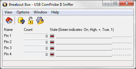
USB: Name - Pin 1, 2, 3, and 4
ComProbe USB monitors four control signals.

ComProbe USB Breakout Box Display
Digital inputs provide a means for users to insert events into the data stream. There are four digital inputs that can be enabled individually.
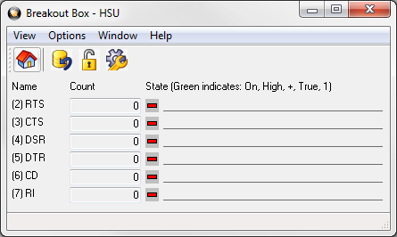
HSU: Frontline monitors six RS-232RS-232 is shorthand for Recommended Standard #232. This is a widely used standard for serial communications defining the physical characteristics of the serial interface and cables. control signals
DTE Signals

ComProbe HSU Breakout Box Display
- DTR - Data Terminal ReadyControl signal most commonly used by the DTE device to signal that it is on and ready. On RS-232 circuits, DTR is usually assigned to pin 20.
- RTS - Request to SendControl signal most commonly used by the DTE device to indicate that it has data to send. On RS-232 circuits, RTS is usually assigned to pin 4. RTS is often used in conjunction with CTS for hardware flow control.